
A wonderful brad-bound catalog and price list, with large glossy pages. Because of the method of binding, the pages appear off-center when isolated, but appear centered when viewed in their bound state.


A wonderful brad-bound catalog and price list, with large glossy pages. Because of the method of binding, the pages appear off-center when isolated, but appear centered when viewed in their bound state.
A three-hole-punched leaflet acting as an abbreviated catalog of Rixford’s wares. This may have been a supplement to an existing catalog, but the composition seems to imply that it was intended as a stand-alone document. Of interesting note is the “Mighty Atom scythe” mentioned as one of the items not depicted, as it describes it as not only being especially lightweight, but that it was available in both American and European “shanks” which we take to indicate as the tang. We have never seen a blade of American form with a European style tang, which would be quite unusual. However, as they are shown listed adjacent to “genuine Swedish scythes” of “Austrian pattern” it seems very likely that they were not the original manufacturer of these, and instead were importing them, possibly from Redtenbacher of Austria.


This prototype universal-fit axe handle is made from split hickory, for perfect end-to-end grain, measuring 1-7/16″ x 3-5/8″ with an overall length of 34″ and the main length reduced to 1-5/8″ wide x 5/8″ thick, with the tongue and swell left at full stock dimension.
The intent is to leave material for the end user to fine-tune the handle to their particular head, while doing the bulk of the time-intensive thinning work for them. The main length is extra broad to permit the end user to make minor alignment adjustments in the handle orientation in addition to at the tongue, and the flat sides of the knob make laminating additional material easier, if desired. The swell is also left broad so that it may be finished to whatever shape the end user most prefers, and by not cutting a kerf it may be cut as the end user sees fit, or not at all (as is traditional for bush hooks.) The head may be positioned more forward or more rearward on the generous block of the tongue/neck to adjust the balance and orient the bit as desired.


A forged rough mockup of our Traveler’s Celt wilderness tool design. Depending on how it’s rigged up, the tool may be used as an ulu knife, chisel, splitting wedge, bark spud, carving spade, axe, adze, and more. This piece does not represent the final intended form of the piece, but rather an initial testing sample prior to having finished pieces produced. The handle here is made from a black locust branch.


NOTE: This is a living document and will see continued updates and adjustments as time permits.
Of all aspects of axes, one of the most-touted but least-understood concepts is how they balance. One often hears that an axe has “good balance” or “bad balance”, but what does that actually mean? Ultimately, all axes are balanced, but the question lies in how that balance impacts the orientation of the handle and the bit in use.
Shown here is a comparative analysis of a classic American style axe (a Council Tools Velvicut 4lb American Felling Axe) alongside two 1300g (2.89lb) Italian axes by Rinaldi: a Calabria and Trento pattern respectively. The grip point on the handle is represented by a blue dot, the center of gravity by a green dot, and the axle as the red line running through them.

The axle is the axis through which the tool will naturally balance and rotate from, and is always represented as a direct line running from the grip point (wherever that may be) through the center of gravity. When the center of gravity lies external to the body of the object, it can be easily found by suspending the object by two different points along with a plumb line. The object will automatically pivot at the grip point to bring the tool into balance. Make mental note of the position of the plumb line, and grip the tool from another point and take a reading of the plumb line again. Where the two plumb lines would intersect in space is the location of the center of gravity. Knowing these dynamics, it is possible to easily analyze any axe without the need to know specific weights or using formulas or computation of any kind.
When people talk about long bits having head wobble (see Cook et al.) they usually make the mistake of measuring from the eye, when really they should be measuring from the axle. As a result, the influence of bit length is often greatly exaggerated, especially when combined with misunderstandings of the effects of curved vs. straight handles.

Having a deep bit allows for deep notches without glancing your cheeks and minimizes risk of barking the neck of your handle against the mouth of the notch. However, it tends to move the handle off a single axis, and so one must be more mindful of which hand is delivering force and how when grasping under the head before a swing, since it creates a plane (triangulation) rather than a simple line. This can be easily compensated for in technique, but one must be aware of it, and ideally one would make a handle with an offset neck to bring as much of the handle as possible along a single axis. Many shipwright’s adzes exhibit just such a neck offset because their manner of use (a third class lever) made it necessary for clean results. This requires starting with a large piece of wood with good grain orientation to be sufficiently strong, and so more commonly one finds axes with relatively straight handles, even with curved American handles.
Note that many American axes could also do with a little more offset in the neck, and that with off-axis handles a change in the grip point will change the presentation of the bit relative to the stroke. This can actually be used to advantage in certain situations. Gripping higher on the handle will yield an axle that presents the bit more open during the stroke, while gripping it lower will present the bit at a more closed angle.


A Calabria and Velvicut axe with the handles altered for ideal offset.
As another way of phrasing the dynamic, imagine you lopped off the rear face of a sledge hammer to reduce its weight, which leaves the eye now at the rear of the head. It would then need the forward face’s angle adjusted slightly to close its presentation to the target and an offset handle to give it the same handling characteristics it had before (though now with less weight.)

Now that we’ve seen how that dynamic plays out, let’s examine how changing different variables impacts the axle, location of the center of gravity, and orientation of the bit.

In the upper left we have an axe or hatchet of fairly conventional orientation and balance, with a short handle. As before, the grip point is shown in blue, the center of gravity in green, and the axle in red. However, we’ve now added the line running between the heel and toe of the bit in fuchsia to help with visualizing the orientation of the bit with the axle.
In the top center, the bit orientation and grip point are held constant, but the bit has been extended. This shifts the center of gravity forward, which pivots the axle forward along with it. In the top right we have the same extended bit, but the grip point has been changed. Because the extension of the bit took the handle more off-axis, the new axle leads to a more open presentation of the bit. The axe has been rotated to put the axle in vertical orientation to highlight this. If, when the bit was lengthened, the handle had been offset to lay along a single axle, the change in grip point would not have resulted in any change in presentation.
In the bottom left, the axe is identical to the one in the top left, but the handle has been extended, effectively closing the presentation of the bit in use despite the head not having been altered in any way. Lastly, in the bottom center and right the heel of the blade has been moved out and then inward respectively.
Lastly, to illustrate that axes with offset necks are not just some theoretical armchair speculation, here are some actual examples of American axe heads fitted to properly offset handles, image courtesy of Axes by G-pig, and used with permission:

Manufacturing such handles on a mass scale, however, would require much larger pieces of wood for blanks, and most axes that have handmade handles running off-axis are generally made that way because it is more expedient and convenient, or possibly because the maker did not even understand these principles and so did not even realize that an offset would be of benefit.
Fortunately, most axes with off-axis handles have a wide enough neck to provide counter-leverage during the two handed span hold. This counter leverage is only needed for a brief moment at the start of the stroke, and is thereafter unnecessary as the hands converge to a practically singular grip point and a natural balance is almost immediately restored. An offset handle, in most instances, merely allows good technique to not require so much mindfulness and is more automatic or “fool-proof”.

The above show the axle of the tool (red line) and corresponding lever arms (blue lines in center figure) of the tool when used with a sliding upper hand (numbered green dots) and fixed lower hand (blue dot.) As previously, the red dot shows the center of gravity, and when the axle and handle diverge the axis along which the hand is sliding is shown by a green line.
On the left you can see that the axe head is balanced by its large poll, and so a straight handle is an appropriate match, with no imbalances imparting torque on the hand in horizontal blows.
The middle axe has the same profile, but the eye has been shifted to the far rear, causing the center of gravity to shift forward in response. This now causes the handle to run off-axis and we can see the lever arms imparting torque on the axle at different points along its length as the upper hand position changes during a sliding stroke. As the hands converge we can see that the lever arm gets shorter and shorter until it becomes essentially insignificant. As such, the infamous “wobble” of a poll-less axe is mostly imparted at the beginning of the stroke, and–while not the ideal–if bearing this in mind it can be compensated for in technique by applying appropriate counter-torque at the start of the stroke and making the slide as early in the stroke as possible.
The third axe now shows the poll-less head with the handle corrected to bring the main length back along a unified axle. This axe will afford the bit size-to-head-weight advantages of a poll-less axe with mostly equal balance to the polled version. One will note that while the axe will now balance properly, the upper hand cannot go as high on the handle as the straight one without running off-axis again. The handle also is trickier to make than in the case of the other two examples and requires better grain alignment to minimize runout.

In case the previous diagrams have been a little difficult to visualize, this diagram simplifies the relationship by eliminating complicating factors. Rather than an “axe” shaped head, we have a simple long, eyeless bar as if the handle were welded to the solid head. The top view shows us the forces at work when the axe is held horizontal. The intersection of the handle’s trajectory and the centerline of the head is shown by the red circle, and the handle treated as massless. A triangle is placed at the point of rotation to indicate the fulcrum forced by the two-point grip. The two sides of this “teeter-totter” are colored to assist in seeing their relative length, and the lines are copied and shown below the head for a clearer comparison.
In the first figure we see a balanced “T” shape, with mass being equally distributed to either side of the center of gravity, and the handle running directly towards it. This tool is in perfect rotational balance.
In the second figure, the handle has been shifted to one side and the lever arms are now imbalanced, causing the longer end to want to drop. The hollow magenta circle marks the center of gravity and the dotted line indicates where the axe would be rotating from if held by the bottom hand only. With the second hand in play, the forced axle of the red line is where the axe will rotate when held/suspended loosely. However, torque applied along the red line will cause the tool to attempt to rotate around the natural axle of the dotted line.
In the third figure, the handle is now offset to align the handle with the natural axle. The red dotted line shows where the handle had previously run in the second figure. The lever arms are now brought back into balance and the “teeter-totter” is now equalled out again.
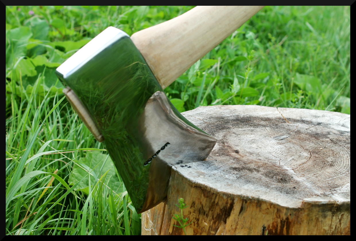
A Condor Michigan axe head ground and polished to a hazy mirror finish, and a high centerline ground in. The handle is an O.P. Link shaved down to shape.


Shown here is a 350g Rinaldi “Calabria” hand axe with a modified handle. A common complaint raised regarding slip fit handles is that (despite their virtues) a knob is either small or totally absent, meaning there is little or nothing to stop the hand from slipping off the end of the handle if a loose grip is used. A simple tapered cross-pin at the end of the handle creates a removable solution to this problem.
A tapered hole was bored with a small step drill and a wooden pin, tapered to match, driven into the hole. The single-sided pin with the projection to the outside of the hand is the most comfortable and secure arrangement vs. a finger-sided or double-sided projection, and if the head must be removed from the handle for use as an independent tool the wooden pin is easily driven out so it does not obstruct the removal of the head. This provides several notable advantages over the use of a lanyard: the user’s hands may slide freely along the handle as needed to adjust grip position, the handle may still be immediately released in the event of an emergency or accident, and the pin allows the end of the handle to be tucked under a belt and have it stay there nicely if the user’s hands need to be free without setting the axe on the ground.


Establishing the actual balance point of asymmetric tools like scythes or axes can be fairly difficult, since the real point of balance often lies external to the body of the tool itself. The following shows a method using a plumb line, two suspension points, and photo overlays to approximate the location of the center of gravity.
Why bother with this, you ask? It depends on the tool. With scythes it can assist in adjusting the horizontal balance or determining the “power” of the unit relative to its overall weight, with axes it can help in determining an ideal head and handle pairing (of particular importance in axes with a minimal or totally absent poll, like the one shown here) and with both tools it can aid in establishing the proper hang of the blade/bit. The axis of rotational balance for an axe will lie along a line passing through both the grip point and the center of gravity.


About the tools: The scythe is a vintage Beardsley grain cradle blade on a Seymour Midwest Tools No.8 aluminum snath while the axe is a Rinaldi “Calabria” Heavy Duty Axe. Check them both out at www.BaryonyxKnife.com!


