Category Archives: The Lecture Hall

The Balanced Axe

NOTE: This is a living document and will see continued updates and adjustments as time permits.

Of all aspects of axes, one of the most-touted but least-understood concepts is how they balance. One often hears that an axe has “good balance” or “bad balance”, but what does that actually mean? Ultimately, all axes are balanced, but the question lies in how that balance impacts the orientation of the handle and the bit in use.

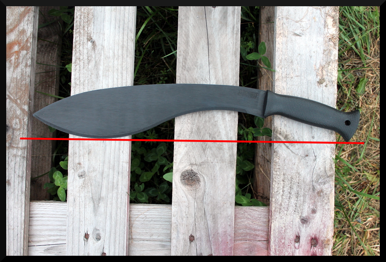
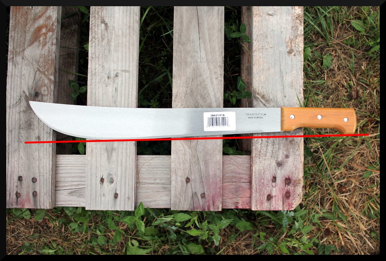
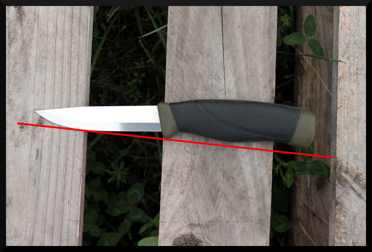
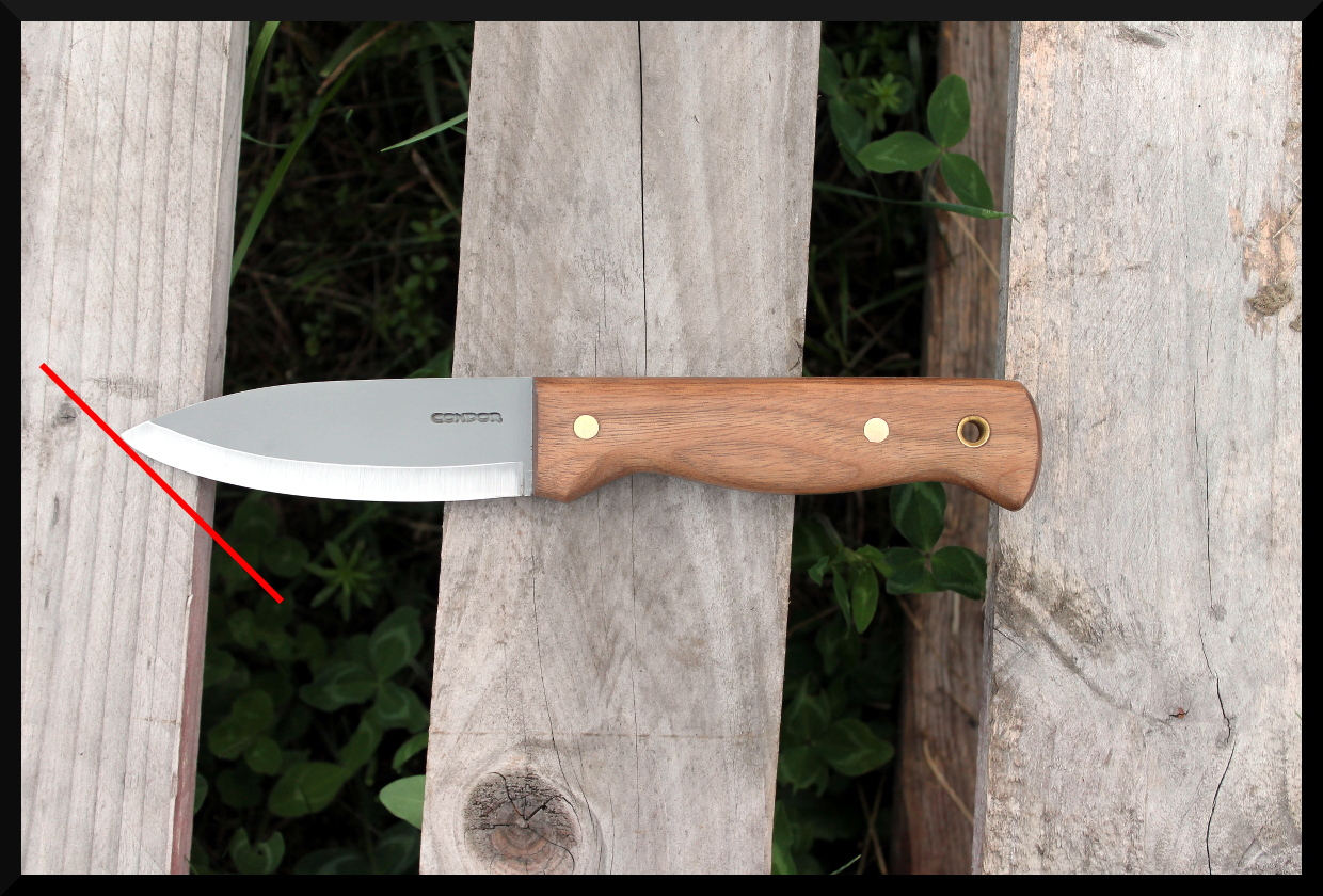
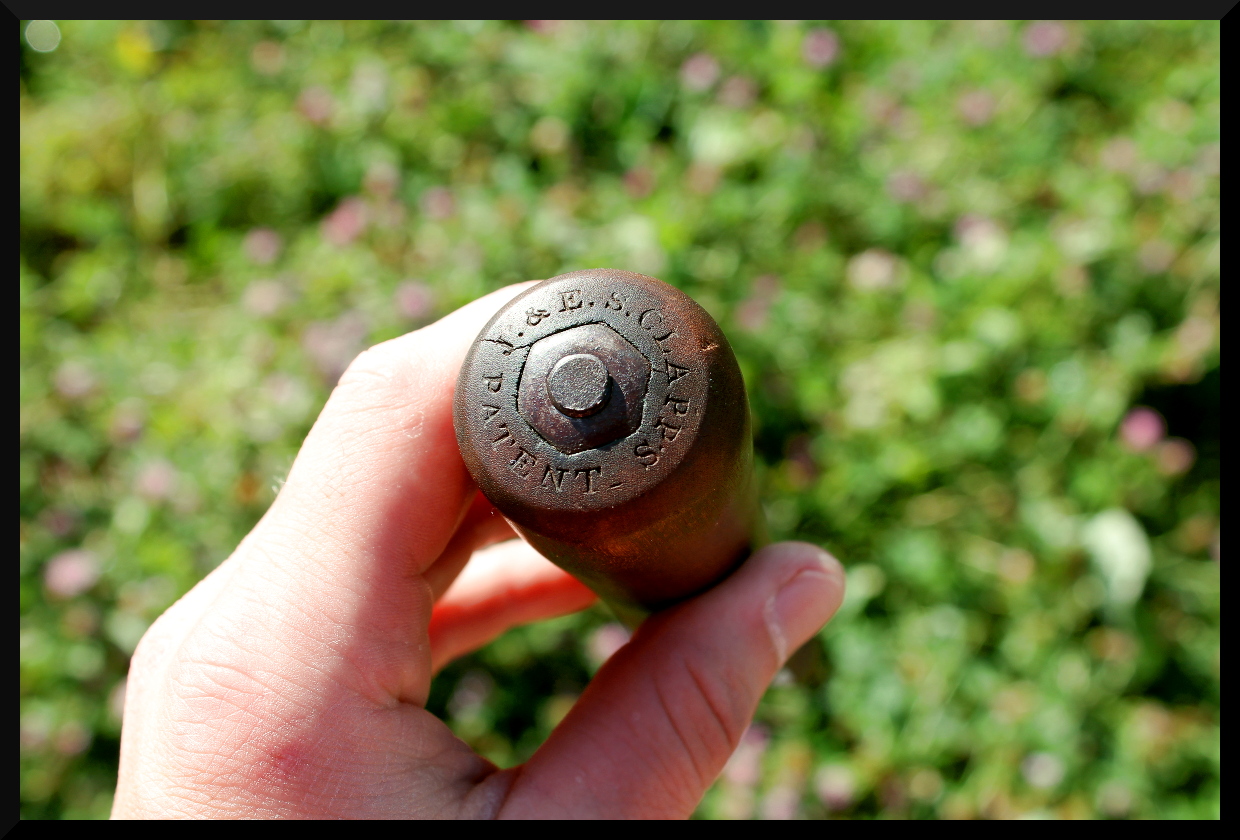
Shown here is a comparative analysis of a classic American style axe (a Council Tools Velvicut 4lb American Felling Axe) alongside two 1300g (2.89lb) Italian axes by Rinaldi: a Calabria and Trento pattern respectively. The grip point on the handle is represented by a blue dot, the center of gravity by a green dot, and the axle as the red line running through them.

The axle is the axis through which the tool will naturally balance and rotate from, and is always represented as a direct line running from the grip point (wherever that may be) through the center of gravity. When the center of gravity lies external to the body of the object, it can be easily found by suspending the object by two different points along with a plumb line. The object will automatically pivot at the grip point to bring the tool into balance. Make mental note of the position of the plumb line, and grip the tool from another point and take a reading of the plumb line again. Where the two plumb lines would intersect in space is the location of the center of gravity. Knowing these dynamics, it is possible to easily analyze any axe without the need to know specific weights or using formulas or computation of any kind.

When people talk about long bits having head wobble (see Cook et al.) they usually make the mistake of measuring from the eye, when really they should be measuring from the axle. As a result, the influence of bit length is often greatly exaggerated, especially when combined with misunderstandings of the effects of curved vs. straight handles.

An overlay of the Velvicut (red), Calabria (blue) and Trento (green) axe heads, aligned at the edge apex.

Having a deep bit allows for deep notches without glancing your cheeks and minimizes risk of barking the neck of your handle against the mouth of the notch. However, it tends to move the handle off a single axis, and so one must be more mindful of which hand is delivering force and how when grasping under the head before a swing, since it creates a plane (triangulation) rather than a simple line. This can be easily compensated for in technique, but one must be aware of it, and ideally one would make a handle with an offset neck to bring as much of the handle as possible along a single axis. Many shipwright’s adzes exhibit just such a neck offset because their manner of use (a third class lever) made it necessary for clean results. This requires starting with a large piece of wood with good grain orientation to be sufficiently strong, and so more commonly one finds axes with relatively straight handles, even with curved American handles.

Note that many American axes could also do with a little more offset in the neck, and that with off-axis handles a change in the grip point will change the presentation of the bit relative to the stroke. This can actually be used to advantage in certain situations. Gripping higher on the handle will yield an axle that presents the bit more open during the stroke, while gripping it lower will present the bit at a more closed angle.

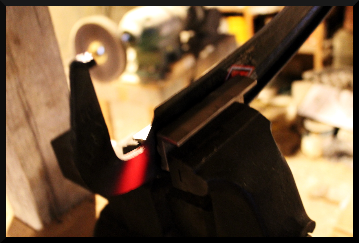
A Calabria and Velvicut axe with the handles altered for ideal offset.

As another way of phrasing the dynamic, imagine you lopped off the rear face of a sledge hammer to reduce its weight, which leaves the eye now at the rear of the head. It would then need the forward face’s angle adjusted slightly to close its presentation to the target and an offset handle to give it the same handling characteristics it had before (though now with less weight.)

Now that we’ve seen how that dynamic plays out, let’s examine how changing different variables impacts the axle, location of the center of gravity, and orientation of the bit.

In the upper left we have an axe or hatchet of fairly conventional orientation and balance, with a short handle. As before, the grip point is shown in blue, the center of gravity in green, and the axle in red. However, we’ve now added the line running between the heel and toe of the bit in fuchsia to help with visualizing the orientation of the bit with the axle.

In the top center, the bit orientation and grip point are held constant, but the bit has been extended. This shifts the center of gravity forward, which pivots the axle forward along with it. In the top right we have the same extended bit, but the grip point has been changed. Because the extension of the bit took the handle more off-axis, the new axle leads to a more open presentation of the bit. The axe has been rotated to put the axle in vertical orientation to highlight this. If, when the bit was lengthened, the handle had been offset to lay along a single axle, the change in grip point would not have resulted in any change in presentation.

In the bottom left, the axe is identical to the one in the top left, but the handle has been extended, effectively closing the presentation of the bit in use despite the head not having been altered in any way. Lastly, in the bottom center and right the heel of the blade has been moved out and then inward respectively.

 Lastly, to illustrate that axes with offset necks are not just some theoretical armchair speculation, here are some actual examples of American axe heads fitted to properly offset handles, image courtesy of Axes by G-pig, and used with permission:

Manufacturing such handles on a mass scale, however,  would require much larger pieces of wood for blanks, and most axes that have handmade handles running off-axis are generally made that way because it is more expedient and convenient, or possibly because the maker did not even understand these principles and so did not even realize that an offset would be of benefit.

Fortunately, most axes with off-axis handles have a wide enough neck to provide counter-leverage during the two handed span hold. This counter leverage is only needed for a brief moment at the start of the stroke, and is thereafter unnecessary as the hands converge to a practically singular grip point and a natural balance is almost immediately restored. An offset handle, in most instances, merely allows good technique to not require so much mindfulness and is more automatic or “fool-proof”.

The above show the axle of the tool (red line) and corresponding lever arms (blue lines in center figure) of the tool when used with a sliding upper hand (numbered green dots) and fixed lower hand (blue dot.) As previously, the red dot shows the center of gravity, and when the axle and handle diverge the axis along which the hand is sliding is shown by a green line.

On the left you can see that the axe head is balanced by its large poll, and so a straight handle is an appropriate match, with no imbalances imparting torque on the hand in horizontal blows.

The middle axe has the same profile, but the eye has been shifted to the far rear, causing the center of gravity to shift forward in response. This now causes the handle to run off-axis and we can see the lever arms imparting torque on the axle at different points along its length as the upper hand position changes during a sliding stroke. As the hands converge we can see that the lever arm gets shorter and shorter until it becomes essentially insignificant. As such, the infamous “wobble” of a poll-less axe is mostly imparted at the beginning of the stroke, and–while not the ideal–if bearing this in mind it can be compensated for in technique by applying appropriate counter-torque at the start of the stroke and making the slide as early in the stroke as possible.

The third axe now shows the poll-less head with the handle corrected to bring the main length back along a unified axle. This axe will afford the bit size-to-head-weight advantages of a poll-less axe with mostly equal balance to the polled version. One will note that while the axe will now balance properly, the upper hand cannot go as high on the handle as the straight one without running off-axis again. The handle also is trickier to make than in the case of the other two examples and requires better grain alignment to minimize runout.

In case the previous diagrams have been a little difficult to visualize, this diagram simplifies the relationship by eliminating complicating factors. Rather than an “axe” shaped head, we have a simple long, eyeless bar as if the handle were welded to the solid head. The top view shows us the forces at work when the axe is held horizontal. The intersection of the handle’s trajectory and the centerline of the head is shown by the red circle, and the handle treated as massless. A triangle is placed at the point of rotation to indicate the fulcrum forced by the two-point grip. The two sides of this “teeter-totter” are colored to assist in seeing their relative length, and the lines are copied and shown below the head for a clearer comparison.

In the first figure we see a balanced “T” shape, with mass being equally distributed to either side of the center of gravity, and the handle running directly towards it.  This tool is in perfect rotational balance.

In the second figure, the handle has been shifted to one side and the lever arms are now imbalanced, causing the longer end to want to drop. The hollow magenta circle marks the center of gravity and the dotted line indicates where the axe would be rotating from if held by the bottom hand only. With the second hand in play, the forced axle of the red line is where the axe will rotate when held/suspended loosely. However, torque applied along the red line will cause the tool to attempt to rotate around the natural axle of the dotted line.

In the third figure, the handle is now offset to align the handle with the natural axle. The red dotted line shows where the handle had previously run in the second figure. The lever arms are now brought back into balance and the “teeter-totter” is now equalled out again.

So You Bought A Seymour No.1 Snath Off The Shelf…

You’ve discovered that it has a few significant problems with it, right? Chances are the taper is noticeably irregular, the neck is as thick as a baseball bat, and you can’t get the nibs to loosen up despite knowing that they’re a left-handed thread because they were cranked on too tight at the factory. But here’s the good news: all of those issues are fixable.

The irregular taper and thick neck of the snath can be fixed with a little time with a spoke shave and rasp, and the nibs can be loosened by using some rubber vise jaw pads to hold the grips of the nibs tightly without marring or cracking them and using the shaft of the snath for leverage to break them loose. There’s one major flaw, however, that’s not as easy to correct…the collar is installed a whopping 20° out of alignment, and when the loop bolt is perpendicular to the ground like it should be, the arch of the snath is pointing right towards you.

It’s not a perfect fix, but you can correct for this by introducing a twist to the tang of your blade much like is commonly seen on European pattern blades. Heat the shank of the tang in same manner you would if you were adjusting its pitch, but instead, lock the tang in a sturdy vise and pull on the blade while the shank is still at heat to introduce a matching 20° twist to the tang. This will correct for the crooked collar to bring the arch of the snath back to vertical. The downside of this is that when adjusting the hang of your blade you’ll now be pivoting the length of the blade along a path that resembles an inverted cone instead of in a nice flat circle like you would with a snath that had the collar correctly mounted, but it’ll at least keep the arch from striking you in the thighs and knees every time you take a stroke with the scythe!

A Seymour No.1 snath as currently assembled from the factory. The blade was bent to correct for the collar misalignment prior to the photo being taken.


End view showing the misalignment of the snath's arch when the collar runs parallel to the ground as intended.
View showing how the corrective bend of the blade's tang brings the arch of the snath back into correct alignment despite the crooked collar.
View showing how the corrective bend of the blade’s tang brings the arch of the snath back into correct alignment despite the crooked collar.

Assessing Form Factor In Cutting Tools: The Line Test Method

When analyzing knife and tool designs there are a wide range of approaches that can be used to develop an understanding of a particular tool’s ideal applications. One of these methods that I’m fond of using when initially sizing up a tool is the line test method. Imagining a superimposed straight line over various points of the tool’s outline is a quick and easy method for establishing rough concepts of tool clearance in use. That is to say, it helps you get an idea of how much space your hand will have in use, what regions of the blade will be making contact at what orientations relative to the target, and if any regions of the blade would be prevented from cutting against a broad flat surface. For instance, if you were cutting atop a chopping block of some kind, many forward curving blades would need to be chopping on a block of a certain height and width in order to deliver a blow along the interior of the blade’s arch without the hand striking the ground.  To demonstrate this method, observe the differences between the following lineup when the test is applied.

LineTestLineup

To begin with, we’ll start the the most basic test–seeing what a line looks like describing a “table” surface, and what the tool would look like laying against it with one point of contact somewhere on the blade and one somewhere on the handle. This is the same as placing the tip of the blade on a table surface and rolling it back until the handle contacted it.


RinaldiZoccaStraightLine RinaldiZoccaStraightLine2 ColdSteelKukriMacheteStraightLine ImacasaPangaStraightLine TramontinaStraightLine ProDynamicStraightLine CondorHudsonBayStraightLine BeckerBK2StraightLine CondorBushloreStraightLine MoraHDCompanionStraightLine SvordPeasantStraightLine OpinelStraightLine

The line test can also be used to assess things like what part of the blade will be in contact with a surface when held at a given angle to it. This is often useful when considering specific task applications where the target will have a certain spacial relationship to the user. I often think of it in terms of if the target will be sitting above or below the elbow, and by how much. The following images show one example of the line test being used to approximate the angle at which the tip contacts the plane surface. However, if you have a particular set of tasks in mind for a knife, imagine the plane formed by a “line of best fit” by your targets and try using the line test at those angles to see if an appropriate region of the blade is being contacted.

RinaldiZoccaTipLine RinaldiZoccaTipLine2 ColdSteelKukriMacheteTipLine ImacasaPangaTipLine TramontinaTipLine ProDynamicTipLine CondorHudsonBayTipLine BeckerBK2TipLine CondorBushloreTipLine MoraHDCompanionTipLine SvordPeasantTipLine OpinelTipLine

The First Modern American Scythe Nibs

Up until the mid 19th century, American scythes had used the English method of affixing their nibs: an iron loop was fastened to the shaft of the snath by means of a wedge driven between the loop and the snath itself. While this allowed the nibs to be positioned at will along the snath, the wedges were prone to working their way loose at inconvenient moments, and in the industrial boom of the mid-1800’s a number of innovations were made in the means of fastening nibs. The most notable of these is the method that eventually became the standard: the so-called “Clapp’s Patent” nib. Patented in 1838 by Joseph and Erasmus S. Clapp of Montague, Massachusetts, it was the first nib known to bear the form that we see so commonly today on almost all snaths, both new and vintage. The nibs made currently by Seymour Midwest Tools are effectively of the same fundamental design.

We were fortunate enough to come into possession of an original example of one of Clapp’s Patent nibs, as well as a contemporary clone by Lamson Co. This company was particularly notable, for its owner and founder, Silas Lamson, is commonly credited with having inventing the steam bent curved snath as we know it today. This innovation is often cited as having been in 1834, though we have documentation that places it as much as 6  years earlier.  An 1830 document declaring his letters patent include, among other innovations, “the mode of fastening the nibs without wedges” although we do not know the specific mechanism used. As can be seen in the following photos, our Lamson nib is nearly identical to the Clapp one. The Clapp patent seems to have been at the center of a court case regarding patent infringement in 1840.

See first the Clapp’s Patent example:

ClappNib3 ClappNib4 ClappNib6 ClappNib7 ClappNib9 ClappNib10 ClappNib11 ClappNib12 ClappNib13 ClappNib14 ClappNib15 ClappNib16 ClappNib17 ClappNib18 ClappNib20 ClappNib21 ClappNib22 ClappNib23

The Lamson Co. nib:

LamsonNib68 LamsonNib69 LamsonNib70 LamsonNib71 LamsonNib72 LamsonNib73 LamsonNib74 LamsonNib75 LamsonNib76 LamsonNib77 LamsonNib78 LamsonNib79 LamsonNib80 LamsonNib81

The Real Douk-Douks

The French Douk-Douk knife is arguably much more famous than the Duk-Duk secret society of the South-Pacific Tolai people from which it derives its name. Photographs and drawings of actual Duk-Duk members (who acted as enforcers of tribal spiritual and civil order sometimes quite brutally) are scarce and difficult to track down amongst the throngs of images to be found of the knives that bear the name. We’ve gathered a number of images and arranged them here for those curious in knowing more about the figure behind the iconic tool.

We do not own any of these pictures. If you are the copyright holder of any of them and wish them to be removed, please let us know.

Duk-DukCultists1 Duk-DukCultists14 Duk-DukCultists9 Duk-DukCultists11

Ron and Elx”Ron and Ella Lucas's photos of Tolai Duk Duk dancers, about 1964, at Navunarm, 10 miles out of Rabaul, these are from a Tamori

Duk-DukCultists15 Duk-DukCultists12 Duk-DukCultists4 P1140514 Duk-DukCultists3 Duk-DukCultists6 Duk-DukCultists7 Duk-DukCultists10 Duk-DukCultists13 Duk-DukCultists8


Solving the Tomahawk Handle Knob Problem

Shown here is a 350g Rinaldi “Calabria” hand axe with a modified handle. A common complaint raised regarding slip fit handles is that (despite their virtues) a knob is either small or totally absent, meaning there is little or nothing to stop the hand from slipping off the end of the handle if a loose grip is used. A simple tapered cross-pin at the end of the handle creates a removable solution to this problem.

A tapered hole was bored with a small step drill and a wooden pin, tapered to match, driven into the hole. The single-sided pin with the projection to the outside of the hand is the most comfortable and secure arrangement vs. a finger-sided or double-sided projection, and if the head must be removed from the handle for use as an independent tool the wooden pin is easily driven out so it does not obstruct the removal of the head. This provides several notable advantages over the use of a lanyard: the user’s hands may slide freely along the handle as needed to adjust grip position, the handle may still be immediately released in the event of an emergency or accident, and the pin allows  the end of the handle to be tucked under a belt and have it stay there nicely if the user’s hands need to be free without setting the axe on the ground.

Right Side Left Side Left Side of Pin Pin viewed with the bit of the axe facing the viewer. Pin viewed with the bit of the axe facing away from the viewer. Angled detail view, right side. Angled detail view, left side.


Finding The Balance

Establishing the actual balance point of asymmetric tools like scythes or axes can be fairly difficult, since the real point of balance often lies external to the body of the tool itself. The following shows a method using a plumb line, two suspension points, and photo overlays to approximate the location of the center of gravity.

Why bother with this, you ask? It depends on the tool. With scythes it can assist in adjusting the horizontal balance or determining the “power” of the unit relative to its overall weight, with axes it can help in determining an ideal head and handle pairing (of particular importance in axes with a minimal or totally absent poll, like the one shown here) and with both tools it can aid in establishing the proper hang of the blade/bit. The axis of rotational balance for an axe will lie along a line passing through both the grip point and the center of gravity.

Plumb line suspended from the lower nib.

Plumb line suspended from upper nib.

An overlay of the images, aligned as well as possible.

The overlay image rotated and positioned to line up the "two" scythes. The intersection of the plumb lines is now visible
The overlay image rotated and positioned to line up the “two” scythes. The intersection of the plumb lines is now visible.

The intersection marked and the overlay removed.


The plumb line from a suspension point at the grip, showing the axis of rotational balance during use.

Taking a second plumb line  for overlay to find the intersection.
Taking a second plumb line for overlay to find the intersection.

The two images overlaid to find the intersection.

The intersecting lines marked and the overlay removed.

Center of gravity marked.
A conventional polled German axe by Adler.

About the tools: The scythe is a vintage Beardsley grain cradle blade on a Seymour Midwest Tools No.8 aluminum snath while the axe is a Rinaldi “Calabria” Heavy Duty Axe. Check them both out at www.BaryonyxKnife.com!

Adjusting the Tang Angle of American Pattern Scythe Blades

American pattern scythe blades traditionally come from the factory with the tang flat, and they are adjusted to the proper angle for the user and their snath by heating and bending for optimal mowing performance. This image series shows our method of going about it, using a Seymour Midwest Tools 30″ grass blade. If you do not have the tools necessary to perform the bending yourself, a local blacksmith, machine shop, or auto mechanic will likely be able and willing to perform the job.

The angle you will need will depend on your height, stance when mowing, the tuning of your snath, how much bend or “lift” there is in the neck of your snath (typically about 25° in most American snaths) and your intended mowing environment. In general a good rule of thumb is that the edge should ride about the thickness of your fingertip above the ground when in mowing stance. A lawn blade may need a slightly lower lay, and if mowing in very heavy or thick vegetation or on bumpy terrain a slightly higher lay may be preferred. See where your blade rides with the tang unbent and determine how much you want to lower it. This will be the amount of bend you’ll be introducing to the tang.

A Seymour Midwest Tools 30" grass blade clamped for bending.
The blade clamped in such a way as to minimize strain on the web during bending.

Clamp the blade securely in a sturdy vise. Care should be taken so that when the tang is torqued the strain is carried by the rib rather than the thin web of the blade (the span between the rib and the edge.) Here aluminum vise pads are being used both to appropriately manage the sites of pressure, but also to avoid marring the blade.

Care must be taken to avoid heating the edge.
Heating the shank with an induction heating coil. An induction heater uses magnetic frequencies to rapidly excite the iron molecules in the steel in only the narrow band contained by the coil.

Heating the shank of the tang to prepare it for bending requires caution to avoid also heating the edge at the heel of the blade. We use an induction heater, which rapidly heats a narrow band of steel within the confines of its electromagnetic coil, but this is an option few will have. A torch (either MAP gas or oxy acetylene) is much more common, but greater care must be taken with them to mitigate heat migration away from the site of application. A raw potato can be stuck on the edge to shield it from the torch flame as it’s applied to the shank of the tang, or the base of the blade wrapped with a soaking wet rag to act as a heat sink. Try to keep the heat as confined to to the shank as possible, as this is where you want the bending to occur. Bring the metal to at least moderate red heat before attempting to bend.

Don't waste time--bend while the steel is hot!
The shank of the tang has been brought to acceptable heat and is now ready for bending.

Now that the tang has been brought to sufficient heat, twisting force needs to be applied to the tang to impart the desired angle of lift–what is known as the “cray” or the “tack” of the tang. A bending fork is the ideal way to do this (it makes it much easier to control the bend) but you can slip a pipe of appropriate dimensions over the tang to do the job as well.

Position the lower prong where you want the bend to be!
Positioning the bending fork. A pipe may be slipped over the end of the tang if a bending fork is not available, though a fork gives the best results.

The bending fork or pipe should be close at hand during the heating process so you can get it in position without losing too much of your heat. Apply your pressure in a smooth and controlled manner so you can gauge if excessive stress is being placed on the blade itself. If resistance becomes too great, reapply heat as necessary. It is ideal, however, to get the tang angle set in a single heat.

Usually between 10-25° is all that's required!
The end results of the bending. This tang has been given about a 12° tack.

After bending, allow the tang to air cool–DO NOT QUENCH. Cooling the blade with water or by other rapid means would harden the steel, rendering it brittle. You want the metal to cool slowly so that it will be soft and tough to better resist strain during mowing, and prone to bend rather than snap if abused. Water may be pooled on the heel of the cutting portion of the blade after bending to act as a heat sink to protect against heat migration through the steel, ensuring the temper is not drawn out of the edge, but be careful not to allow it to boil up onto the tang portion where it could cause accidental quenching and hardening.